And because the device wasn't very hard to build I dicided to put it on my homepage.
The circuitboard can be ordered at "de ELEKTUUR" (http://www.elektuur.nl/); and order "980077-1 print toerenteller" for FL. 26,05.
The "cockpit"- housing can be ordered at Conrad (ordernr. 842230-33) for FL 8,95.
| Parts list Resistor: R1,R2 = 2k2 R3= 22 M R4 = 15 M R5 = 22 k R6 = 100 k R7 = 22 k P1 = 50 k adjust (vertical) Condensators: C1 = 10 u/16 V radial C2, C3 = 10 n (stab 5 mm) C4 = 100 n (stab 5 mm) Semi-conducters: D1...D13 = low-cuurent-LED green D14...D16 = low-cuurent-LED yellow D17...D20 = low-cuurent-LED red IC1,IC2 = LM3914 IC3 = TLC555 Various: JP1= 2 pole contactrow + jumperhousing (Conrad ordernr.: 842230-33) Ciruit board: ordernr. 980077-1 (WWW.ELEKTUUR.NL) Pickupcoil: see text |
|

Building a revolutioncounten should be
unnecessairy.
Because I think every manufacturer of cars, bikes and
mopeds should mount a revolutioncounter as standard.
But for a
moped-driving electronics hobbyist should there now is a way to change
this.
Setup
The constuction of the electronical
revolutioncounter can be done in different ways.
The main difference is
in the readout of the instrument.
Rougly there are three ways to show
the rpm: with
figures using a few sevensegment-displays, with a analoge scale consisting
of a LED-bar, or with the old-fashion turningcoilinstrument with a
indicator.
The last one of the three is the easiest to realise, but is
also a bit vulnerable and shocksensitive.
So for a moped a readout like
that isn't very suitable.
A indicator with sevensegment-displays is a
real thing for pricisionfreaks, but for this application a digital readout
isn't handy.
Because accuracy as high as that isn't necessary and it
would also make the circuitboard way more complex.
A LED-readout has
the adventage that it's durable and easy to build. We can use one of the famous steer IC's for this
revolutioncounter which can, without using a lot of external compontents,
use an anologe tension to display a LED-bar.
We can use one of the famous steer IC's for this
revolutioncounter which can, without using a lot of external compontents,
use an anologe tension to display a LED-bar.
If we would take about 20
LED's for this, the accuracy of the indicator should be more than
adequete.
The only thing we need now, is a sensor which delivers pulses
which correspond to the rpm, and some
electronics which converts the number of pulses into a proportional direct
current for the LED-bar.
Als you will see, that part is a peice of
cake.
From RPM to DC
For
starters we have to have a suitable recorder wich produces a puls every
engine-revolution.
This can be done in different ways, but the easiest
by far is using a coil to pick up the ignition pulses
inductive.
Because the ignitionpulses are pretty strong, it's
sufficient to wind an ordinary wire 10 or 20 times around the sparkplug
cable.
The ignitionpulses are stong, but they differ a lot in the shape
of their tensionpeaks.
To get reliable countingoulses out of them, the
recordercoil has to be followed by a suitable pulsformer which changes the
signal into a series of neat sigle-shaped pulses.
Only this way you can
make certuin that acidental variations in the width or amplitude don't
influence the countingresult.
Take a look at figure 1, in which the
entire circuit board of the revolution-counter is displayed.
The
pickupcoil has to be connected to C3.
This condensator functiones in
combination with R3/R4 as a differentiator, thus cutting down the ignition
pulses to usable triggerpulses - this is done to prevent accidental double
triggering of the revolutioncounter. These modified pulses are then fead to the
trigger entrance of on of the as monostable mulivibrator linked 555
(IC3).
These modified pulses are then fead to the
trigger entrance of on of the as monostable mulivibrator linked 555
(IC3).
This IC then creates pulses with a fixed (with P1 adjustable)
width
The only thing we have to do now to get a
revolution-dependant-direct curent, is itegrating the pulssignal given by
IC3.
Therefor we use a simple lowpassfilter, als done here with R6 and
C1.
This filter also makes sure that short vibrations in the pulssignal
are "flattend out", because they would make the readout unnecessary
unstable.
LED-Readout
To realize the readout we, just as
for the pulsformer, used and old acquaintance, namely the LM3914 display
driver.
This IC was specialy designed for this purpose and contains a
referance-tensionsource and am accurate ten-times tensiondealer.
From
the connectionpoints of the tensiondealer ten comparators are driven and
in such a way that a next comparator becomes active when the
entrancetension of the IC increases.
The comparatorexits are capable of
driving a LED directly.
The LED-bar formed this way can be set to
"dot"- or "bar"-mode; in the first case pen 9 has to be left "open" and in
the second case it has to be connected to the tensionpuls.
Here we have
chosen for the second possibility.
A nother nice caraceristic of the LM3914 is that it's
very easy to link two together is a LED-bar with a higher resolution is
wanted.
Because the maximum of ten LED's is a bit low in our case, we
used this possibility gratefully.
As the shceme shows, this resulted in
a 20 LED-display, in which, depending on the setup, every LED represents
about 500 rpm.
You can use
different color LED's and you can make for instance a "safe" (green) area
of 500...6000 rpm
(D1...D12), an "attention" (yellow) are to 8000 rpm (D13...D16) and a
"prohibiten" (red) zone between 8500 and 10.000 rpm
(D17...D20).
But ofcourse you can also make your own scale which is
completely different.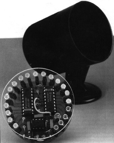 Practical things
To make the building
realatively easy for amateurs, we designed a compact circuit board for the
revolutioncounter, which is shown in Figure 2.
When we held a little
servey here, we found out that everybody prefered a round scale, and that
is why we placed the 20 LED's in a circular shape on the cicuit
board.
Since the revolutioncounter has very little parts, the
construction of the circuitboard doesn't need a lot of
explanation.
Just neatly solder all the compononts in the parts list,
and voila!
Jumpercontact JP1 was added so you are able to check the
counter after the construction.
If pulses are added to C3, a tiny
direct current should be measurable at the first contact of JP1 which can
be altered using P1.
If this works, the chances that the pulsformer
works are very good.
If you connect an adjustable
directcurrent-powersupply of a few volts on the other side of JP1, the
LED-bar should come to life; this way you can check the readout
part.
Normaly a jumper will be put on JP1.
We've allready talked
about the pickupcoil.
It could be possible that this part needs some
experimenting, but normaly the inductive pick up of ignition pulses from
the sparkplugcable shouldn't be any trouble.
The connection between the
coil and the entrancepen of the circuitboard kan be made with a normal
piece of wire.
Another thing about the round shape of the circuit
board.
Besides our personal preference, there was another reson to
choose this form.
Browsing through various catalogs we came uppon a
nice housing, which has a shape that fits nicely in the instrumentpanel of
most mopeds and motocycles.
That's why we adjusted the dimensions of
our circuit board to it.
In Figure 3 you can see this so called
"cockpit"-housing, together with a test model op the build circuit
board. Power
Power
We haven't talked about the way to
power the revolutioncounter..
Als shown in the scheme, it's designed
for a 5 V feed (6V is no problem).
But the power has to be reasonably
"clean" and stable, so you shouldn't connect it directly to the moped
unless it has a battery.
If you do want to use the available power
(which is very handy ofcourse), you will have to place a 5V stabelizer
between the moped's power and the revolution counter.
The nessecary
extra circuit board for this is can be seen in Figure 1 (it's the one with
the dotted line around it.
Because the available power (6 a 7 V) is
about 1V above the prefered 5V, you should in this case use a
low-drop-power-regulator like the 4805; so a normal 7805 can not be
used!
If you want it to be completely self-supporting (so not connected
to the moped), you can use a battery.
Four rechargeable penlights are
perfect as a powersource and will endure a pretty long time.
A
stabelizercircuit isn't necessary then.
And if you want the battery's
to last even longer, you should set both LM3814's in to
"dot"-mode.
This can be done by not soldering pen 9 of IC1 and
IC2.